Benefits of CAE Technology for Engineering Managers
As products become more complex, engineers will need computer-aided engineering (CAE) tools like model-based systems engineering (MBSE), finite element analysis (FEA) and computational fluid dynamics (CFD) to create realistic digital prototypes.
There are a number of important trends that are changing the way design teams use CAE:
- Simulating complex products early in development cycles with MBSE
- CAE vendors are democratizing simulation with tools like apps and templates
- More engineers in development teams require simulation training
- The upfront cost of simulation is reduced, thanks to the cloud and alternative licensing
- The use of topology optimization to reduce the weight of a product
- The rise of vendor-agnostic organizations pushing for change in the CAE industry
MBSE Brings Simulation and Verification Early into Your Team’s Design Cycle
MBSE allows engineers to keep track of the whole system they are creating. Information, from tolerancing to simulation results to alternative CAD drawings, can all be added to the MBSE.
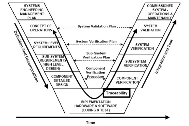
System V diagram shows the steps of system-level thinking. (Image courtesy of Wikipedia.)
“At its heart,
MBSE relies on dynamic 3D CAD models that include all of the subsystem definitions,” said Scott Leemans, principal engineer at Advatech Pacific. “The design starts with a generic model, upper left of the [System V diagram], that is then better defined as details are fleshed out. The output at the bottom left side of the [System V diagram] is component-level functions, dependencies and interfaces that are all described in high-fidelity detailed component models.”
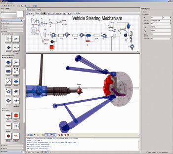
System level simulation in MapleSim features drag-and-drop functionality. (Image courtesy of Maplesoft.)
One of the biggest advantages to MBSE is the ability to model the whole systems using equations called 1D or 0D simulations. When engineers bring this system-level simulation earlier into the design process, they can better assess the product’s design space. This will help to eliminate design paths while discovering more optimal and innovative options.
As MBSE programs tend to use drag-and-drop interfaces and simplified physical models, they do not have a large learning curve like many 3D simulation software like FEA and CFD. However, though MBSE is able to look at the big picture of your design, it isn’t able to look into the nitty-gritty detail like FEA and CFD. The aim is to quickly run through simulation and eliminate design paths.
“1D simulation models usually possess a higher degree of abstraction and require a small amount of input data (compared to 3D models),” said Michael Hoffman, senior vice president for math and systems at Altair Engineering. “Thus, they are ideally suited for system investigation in the concept phase. However, due to the higher degree of abstraction, they may lack some accuracy [that] is required in the detailed design phase; that’s where people use more 3D models. The challenge is how to synchronize these models and how to realize a seamless transition from 1D to 3D.”
“We can link simple 0D and 1D models of systems engineering and pass those results through to the 3D high-fidelity models so the complete design process is done through a systems engineering perspective,” said Joe Walsh, CEO of IntrinSIM.
In other words, FEA, CFD and MBSE can be used hand in hand. And they can also be used to feed information back into each other to help increase the accuracy of your system simulations.
“In the FEA world of simulation, you typically test the reaction of individual parts of a system to a set of forces. In a lumped parameter modeling system like MapleSim, you generally determine what those forces might be,” said Chad Schmitke, director of MapleSim development. “MapleSim quickly simulates the system and determines how it would operate as a whole. The forces involved can then be tested in the FEA framework.”
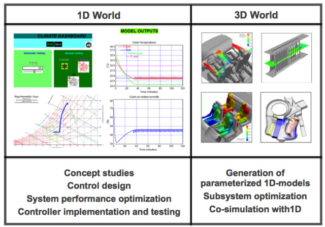
Integrating 1D and 3D simulations. (Image courtesy of Altair.)
“There are
scales that a company will look at to optimize the product, from subsystems, to components, to the whole system,” said Dennis Nagy, principal at BeyondCAE, a consulting service. “Using simple system-level models, you can determine some initial configurations of the design and then cascade these findings down to the more detailed simulations like FEA and CFD.”
Simulation companies that are expanding their simulation portfolios to look toward the system include ESI Group, PTC, Dassault Systèmes, Altair, MathWorks, Maplesoft and ANSYS. If MBSE is a tool you wish to integrate into your design cycle, then looking at those organizations might be a good place to start.
Adding CAE to Development Cycles with Apps, Templates and Simulation in CAD
As engineers find out more about their products as a system, they will eventually need to look closer into the individual parts. This is where 3D simulations like FEA and CFD come into play.

Simulation apps limit the inputs users can make, allowing experts to ensure that CAE novices can’t break the analysis. (Image courtesy of COMSOL.)
These 3D CAE tools have not been traditionally easy to use. In fact, experts and analysts are often used to ensure that the information going into the tool will create accurate and meaningful results. Unfortunately, these simulation gurus are often overworked as all the hard simulation work falls upon their desks.
Recent trends in the simulation industry are allowing for the democratization of CAE technology. Tools like simulation apps, templates, fit-for-purpose simulation tools and simulation in CAD are making it easier for nonsimulation experts to be capable when using the technology. Additionally, CAE vendors have also been busy updating their UIs to accommodate ease of use.
These changes to the CAE world have alleviated much of the load on simulation analysts and allowed them to share their expertise to a wider audience. There are, however, benefits and drawbacks to each democratized CAE option that will affect which option management chooses to implement.
“Take engineers spending their whole time designing pumps; they don’t need to learn Nastran, Abaqus or ANSYS in general. They just need to know how to use [CAE] for pumps,” said Nagy. “So someone can make a streamlined vertical app that works just for pumps. This app can then ask the engineers the correct questions to perform the simulation in the background.”
When an analyst creates a simulation app, they are essentially creating a small sandbox where a user can create a simulation with limited control on the inputs. Most of the inputs, pre-processing and post-processing will already be set up by the analyst under the hood of the simulation app. These safeguards reduce the risks of errors as an analyst can prevent a bad combination of inputs within the apps’ programming.
“The [COMSOL] application builder lets you take a complete simulation and turn it into an app. So you set up your model, but then you can choose exactly what you want the app user to be able to change,” explained Lexi Carver, technical marketing engineer at COMSOL. “For instance, you might share that [app] with a colleague who doesn't have a background in simulation, or doesn't have a background in the physics that you're working in, or you might share it with a customer. A colleague or a customer can change one or two parameters and test different designs without actually needing to know all the background and all the modeling that went in underneath.&
To bring simulation apps into your workflow, you can ask a consultant, like Comet Solutions, to create one tailored to your organization. Or you can hire an internal expert who can then use a CAE product that includes simulation app authoring abilities like COMSOL or Comet Solutions’ SimApp Authoring Workspace.
Simulation templates, in contrast, tend to give the end user a little more control over the analysis process. Depending on the simulation platform being used, an analyst can modify the UI and workflow, and automate a lot of the parameter selection.

Template used to modify the arm length of a part and automatically update the remainder of the part. However, as the user still has access to Siemens NX, they still have quite a lot of control over the analysis. (Image courtesy of Siemens PLM Software.)
“The analyst will want others to use their basic framework without exposing them to all the details that advanced analysts might need,” said Ganesh Sethuraman, senior marketing manager at Siemens PLM Software. “[
Siemens PLM’s Product Template Studio] opens the door of high-end CAE tools to others who are less experienced in simulation.”
Traditionally, making these templates would have required programming skills. However, new tools exist that allow analysts to create templates without coding.
As the template is used in the simulation platform directly, many of the platform’s features will still be accessible by the engineer. This does allow for more freedom but also increases the risk of garbage in, garbage out. As a result, templates are best suited for engineering teams with a working knowledge of CAE tools.
For more on simulation templates, look toward
Siemens,
Dassault Systèmes,
ANSYS and
Autodesk.
A compromise between the use of apps and templates in the simulation industry is to instead use fit-for-purpose CAE tools. Traditionally, simulation platforms have been general purpose. Though this gives the user the freedom to simulate any system the CAE tool is able to emulate, it also requires a lot of training before you can take off with an analysis. By making fit-for-purpose simulation tools, CAE vendors can provide a program that lets users in a particular field take off quickly.
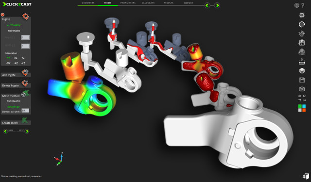
Fit-for-purpose simulation tools like Altair’s Click2Cast introduce CAE tools that are tailored to a specific task or industry. (Image courtesy of Altair.)
“You can’t be all things to all people,” said Nagy. “Simulation vendors will either need to focus on general purpose tools or tools that are specific for specific people.”
Fit-for-purpose CAE tools use workflows, language and interfaces that are comfortable to an engineer working in the specific niche the tool is specialized in. This reduces the learning curve of the tool. Additionally, as the tool is tailored to a task the engineer is already an expert in, there will be less chances of errors.
Unfortunately, if you ever need the expanded use of the full simulation software, it will not be there when using a fit-for-purpose tool, or a simulation app, for that matter.
Examples of fit-for-purpose engineering simulation tools are numerous. However, some interesting examples include ESI Group’s portfolio of stamping, welding and seat simulation software, and Altair’s Click2Cast.
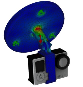
Simulation of a camera mount in SOLIDWORKS Simulation. (Image courtesy of Dassault Systèmes.)
Another way to add CAE into your design cycle is to have it accessible within your CAD environment. The clear benefit is that the design team will have an easier time using the simulation software as it is in a UI they are familiar with.
“We see SOLIDWORKS as a design to engineering tool. One of the main advantages of it is that simulation is integrated into CAD during the design workflow,” explained SOLIDWORKS Simulation expert Glenn Whyte, a Simulation product manager at Hawk Ridge Systems. “This will shorten the learning curve.”
“We explain to our customers that have never done analysis before that they can analyze four–five different scenarios in an hour just by manipulating the CAD, processing the analysis, and keeping track of what those changes mean physically,” added Whyte. “Simulations are also completely integrated with the CAD model. If you make a design change, then it is ready to analyze without intermediate steps like file exporting.”
However, this option doesn’t include a simulation expert holding a designer’s hand. Therefore, this option is best reserved for design teams with a good understanding of the physics related to the product.
Some examples of organizations moving in this direction include Siemens PLM Software, Dassault Systèmes SOLIDWORKS and Autodesk Nastran In-CAD. You can also look at tools that integrate into CAD software like COMSOL’s LiveLink for SOLIDWORKS.
Training Your Engineering Designers to Use Simulation
Image from a NAFEMS structural optimization training course on FEA. (Image courtesy of NAFEMS.)
Even if you do hire a simulation analyst, you will need to have many on your
team trained and knowledgeable about how simulation tools work and how to use and interpret them properly. This is especially true if these engineers will be basing decisions on the simulation results or using the software directly.
Much of this training and continual education will come in the form of technical papers, videos and guides from organizations like CAE vendors, academics and government agencies. Additionally, CAE nonprofit organizations like NAFEMS also offer CAE courses to engineers.
After all, it is in your vendor’s best interest to train as much of your team as possible to ensure that more software seats are sold. As a result, they are often a good place to start an employee’s CAE education.
CAE vendors will often have their own training website filled with how-tos, help desks, discussion boards, videos and software manuals. Many will also hold training sessions in major cities and at conferences.
“You can give away as much software as you want, but if you don’t provide training and support, it will sit there and not be used,” said Paul Lethbridge, academic program manager at ANSYS. “We offer a lot of material to our partners to ensure the product doesn’t end up as shelf-ware.”
When looking into how to simulate a specific phenomenon, it might be best to look at the technical papers produced by academics and government agencies. These two types of researchers release a lot of their work in the form of patents and papers. These could be great sources to ensure that your team is simulating properly.
Simulation Becomes More Affordable for Tight Engineering Budgets
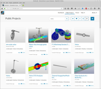
Screen shot of SimScale’s CAE platform on the cloud.
Unfortunately, expertise and training isn’t the only hurdle to bringing 3D simulation like FEA and CFD to your design team?
Your organization will need high performance computing (HPC) to run the computationally heavy simulations and user licenses required to get the programs operational. Traditionally, these have been very expensive.
To lighten the expense of HPC, many simulation tools now use graphics cards, or GPUs, to crunch the large simulation data. This allows for more compute power from the lowly workstation. Some simulation organizations going down this road include Altair, ANSYS, Siemens and Dassault Systèmes.
Additionally, many organizations are now offering pay-as-you-go cloud computational services that offer engineers the power they need without the heavy investment of a traditional HPC computing architecture. Some will even host the whole CAE platform on the cloud while offering token or pay-per-use licenses, reducing the cost of entry. Many of the simulation big players like Dassault Systèmes, ANSYS, Autodesk, Siemens, COMSOL and more have a cloud option.
Though many of these cloud options may be affordable for medium to large businesses, smaller operations might still see these CAE providers as too far out of their price range. To combat this, a series of smaller CAE companies, like SimScale and Simulation for Design, have popped up, offering their services on the cloud with drastically reduced licensing costs.
These organizations offer simulation technology at a price that is much easier on the budgets of small to midsize businesses. Don’t expect to see the same breadth of functionality you will see from a major simulation player. However, these products will be able to fill many of the basic FEA needs of a small to medium-sized engineering operation.
David Heiny, a product manager at SimScale, said, “The core idea behind the SimScale platform is to take down the barriers in terms of up-front financial investment to start using simulation.”
“Simulation for Design is getting a lot of interest from a wide user base thanks to its simplistic approach and low, straightforward price point. For 10 bucks, users can start a simulation,” said Walsh of IntrinSIM.
Finally, managers can also choose a private cloud computing company to crunch all of their computations. One organization that specializes in crunching this simulation data from various vendors over the cloud is Rescale. You will still need a license to run the simulation; however, Rescale does sell licenses to many of the CAE software packages they are compatible with.
Topology Optimization Driven by Simulation Technology
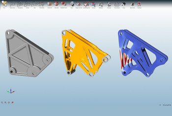
Screenshot of a topology optimization using solidThinking Inspire. (Image courtesy of Altair’s solidThinking.)
Another way to bring simulation early into your design cycle is with topology optimization tools.
These tools use structural simulations, often under the hood, to automatically build an optimized part. All the user needs to provide for the software is the space the part will occupy and the loads it will experience.
Though this technology has been around for a while, it has started to take off more thanks to the use of 3D printing. With the use of 3D printers, engineers can manufacture designs that were previously impossible to construct any other way.
As many of these tools will be targeting early-stage design engineers and not simulation experts, these tools often have easy-to-learn workflows. Some CAE providers will also offer two package options for this technology: one that targets the designers with a simplified UI and another for analysts that gives the user more control over the simulations.
“For the design engineer, they don’t want to mess with anything. They want to make it easy to use and understand, but for the analyst, they want full control,” said Doug Wenk, director of product management at Siemens PLM Software.
As a result, the engineer now has the freedom to create parts that are highly optimized to a part’s load history without worrying about how that part will be produced. In theory, this should make parts that are stronger, lighter and further optimized for their tasks.
Topology optimization is an early stage design tool. As a result, the engineer will still need to put in work to verify and tweak the part into its final iteration. But using these relatively easy-to-use tools, your design team can start using a near-optimized part instead of going with their gut or last year’s model.
“Programs like Inspire perform these topology optimizations in an effort to cut down the development cycle,” said Jaideep Bangal, senior application engineer at solidThinking. “After using Inspire, much of the design is already completed. Engineers need only to put the finishing touches on the model.”
If you are interested in bringing these topology optimization tools into your early design cycle, then you might want to first look at Siemens, Dassault Systèmes and Altair’s OptiStruct and solidThinking Inspire.
CAE Industry Experts Are Expanding Simulation to Reach Industries Like Yours
(Image courtesy of ASSESS.)
(Image courtesy of NAFEMS.)
Adding simulation technology into your workflow may at first sound overwhelming. Hearing this from many users, the simulation industry is taking steps to simplify the adoption of the technology.
This democratization of CAE tools has been aimed at small to medium-sized businesses that traditionally do not have the capital and expertise to adopt CAE.
As a result, vendor agnostic CAE organizations have been working to advance the democratization trend like NAFEMS and the
Analysis Simulation, and Systems Engineering Software Summit (ASSESS).
For instance, NAFEMS has released a series of simulation buying guides that point organizations to the right tool for their jobs. These documents address how organizations can buy and choose FEA services, systems and pre-/post-processing, and how they can use and understand the results.
Additionally, ASSESS gathered representatives of CAE vendors, thought leaders, industry, academic and government to discuss the CAE industry trends, including democratization. The vision of ASSESS is to provide anyone who can benefit from simulation with access to it. In their discussions, they set a goal to extend the use of CAE tools by an order of magnitude within the next five years.
As a result, expect to see more movement toward democratization from CAE vendors that work with NAFEMS and ASSESS. Since these vendors will be courting small to medium-sized businesses to use their CAE technology, now is the perfect time for your engineering team to jump in.
To learn more about CAE tools and how to bring them into your development cycles, read the following white papers:
Create your own user feedback survey